FM-SER FACE Module provide various serial connectivity solution and compatible with several Compulab systems. Refer to Compatibility Matrix for products fit.
Highlights
- High performance UARTS
- Asynchronous baud rates up to 15Mbps
- 128-byte deep TX/RX FIFOs
- Advanced FIFO fill management
- RS232, RS485, RS422 operation
- Programmable RS485 turn-around delay
- 450 through 950 software compatibility
- Two independent CAN bus controllers implement CAN V2.0B at rate of up to 1Mbps each
- Isolated PHY with rated isolation voltage of 2.5 kV RMS
| Connectivity | Specifications |
|---|---|
| RS232 / RS485 / RS4221 | 6x RJ-11 jacks functioning as RS2322, full-duplex RS485 or RS422 serial ports; |
| CAN bus | 2x RJ-45 jacks functioning as an isolated Controller Area Network (CAN) bus |
Notes:
- The default standard can be configured by jumper E1. See section Serial Ports Configuration.
- FM-SER is classified as DTE (Data Terminal Equipment) in terms of RS232 standard definition.
Block Diagram

Hardware Specifications
The following section provides information about the main components and respective features, as well as available configuration options.
PCIe to UART Bridge PLX OXPCIe958
- UART bridge – from PCIe to 8 serial ports1
- Eight 128-byte transmit and receive FIFO unit
- Integrated DMA controller
- Asynchronous data rate of up to 15.625 Mbp
Note:
- FM-SER utilizes 6 serial ports
LTC2872 Dual Multiprotocol Transceiver
- Three dual transceivers are onboard the FM-SER provide 6 multiprotocol serial ports.
- Implementation of physical layer (PHY) of RS232 or RS485 serial protocol ports.
- Up to 500kbps data rate from UART to RS232 and up to 15 Mbps data rate to full duplex RS485
- Supports RS422
- Integrated termination resistors are being switched according to mode of operation.
- Loopback mode for self-testing
CAN Bus Controller MCP2515
- Connected to SPI bus originated from a USB to SPI bridge
- Two CAN bus controllers implement CAN V2.0B at rate of up to 1Mbps each.
- Six 29-bit filters, two 29-bit masks and two receive buffers with prioritized message storage
- Interrupt outputs from CAN bus controllers and a shared reset input are connected to the host motherboard.
CAN PHY ADM3053 (Isolation Driver)
- Isolated physical layer (PHY) transceiver with rated isolation voltage of 2.5 kV RMS for 1 minute
- Data rate of up to 1Mbps
- Consumers power from the CAN bus by default, and can be configured to supply power of up to 170 mA to the bus.
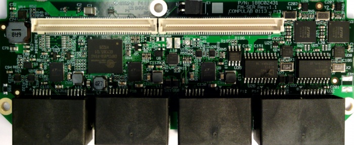
RJ-11 Serial Ports
The serial ports arranged as COM ports differently on different motherboard configurations, as detailed in Table 2. The physical locations of the ports are depicted in Figure 1.
Serial Ports Arrangement
| Motherboard | P1 | P2 | P3 | P4 | P5 | P6 |
|---|---|---|---|---|---|---|
| fit-PC3/ SBC-fitPC3 | 9 | 8 | 5 | 4 | 7 | 6 |
| Intense-PC/ SBC-iSB | 10 | 9 | 6 | 5 | 8 | 7 |
RJ-11 Pinout
| RS232 1 | RS485 2 | |||
|---|---|---|---|---|
| Pin # 3 | Type | Functionality | Type | Functionality |
| 1 | O | RTS | O | TX- |
| 2 | – | GND | – | GND |
| 3 | O | TX | O | TX+ |
| 4 | I | RX | I | RX+ |
| 5 | – | GND | – | GND |
| 6 | I | CTS | I | RX- |
Notes:
- FM-SER is classified as DTE (Data Terminal Equipment) in terms of RS232 standard definition
- FM-SER supports only full duplex RS485 (half duplex not supported)
- The port numbering is specified in Table 2
RJ-45 CAN Bus Pinout
| Pin # | Type | Functionality |
|---|---|---|
| 1 | IO | CAN + |
| 2 | IO | CAN – |
| 3 | – | CAN GND |
| 4 | NC | NC |
| 5 | NC | NC |
| 6 | – | GND |
| 7 | PWR | CAN GND |
| 8 | PWR | CAN VCC |
Configuration
Serial Ports Configuration Each serial port can be individually configured to act in RS232/RS485 full duplex modes. The configuration is selected in fit-PC3 BIOS setup. The default selection between RS232 and RS485/RS422 is determined by E1 jumper position. Default mode determines the power-up state of the Dual Protocol Transceiver. It is applied to all ports and remains valid in case that software configuration is not performed. The options of jumper E1 selections are detailed in Table 4.
Jumper E1 options
| Jumper Position 1 | Default Serial Protocol |
|---|---|
| Assembled | RS232 |
| Removed | RS485 / RS422 |
Note:
- The jumper is assembled by default
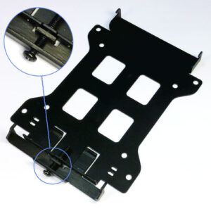
Jumper E1 location 
After power-up, any individual port can be configured using software controlled SMBus system management protocol.
CAN Bus power supply By default, the FM-SER consumes power from the CAN bus. After power-up, the power supply option can be determined by a GPIO line connected to the motherboard, and is fully software controlled.
| Weight | 0,000 kg |
|---|---|
| Dimensions | 0,00 × 0,00 × 0,00 mm |
FACE-module – FM-SER (6x UART)
5 in stock (can be backordered)
950,00 kr. 1.187,50 kr.
Related products
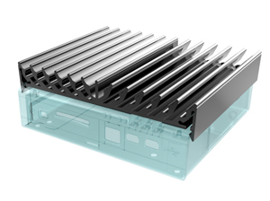
Airtop
fit-PC
FM-SER (6x UART)
950,00 kr. 1.187,50 kr.
5 in stock (can be backordered)
FM-SER FACE Module provide various serial connectivity solution and compatible with several Compulab systems. Refer to Compatibility Matrix for products fit.
Highlights
- High performance UARTS
- Asynchronous baud rates up to 15Mbps
- 128-byte deep TX/RX FIFOs
- Advanced FIFO fill management
- RS232, RS485, RS422 operation
- Programmable RS485 turn-around delay
- 450 through 950 software compatibility
- Two independent CAN bus controllers implement CAN V2.0B at rate of up to 1Mbps each
- Isolated PHY with rated isolation voltage of 2.5 kV RMS
| Connectivity | Specifications |
|---|---|
| RS232 / RS485 / RS4221 | 6x RJ-11 jacks functioning as RS2322, full-duplex RS485 or RS422 serial ports; |
| CAN bus | 2x RJ-45 jacks functioning as an isolated Controller Area Network (CAN) bus |
Notes:
- The default standard can be configured by jumper E1. See section Serial Ports Configuration.
- FM-SER is classified as DTE (Data Terminal Equipment) in terms of RS232 standard definition.
Block Diagram
Hardware Specifications
The following section provides information about the main components and respective features, as well as available configuration options.
PCIe to UART Bridge PLX OXPCIe958
- UART bridge – from PCIe to 8 serial ports1
- Eight 128-byte transmit and receive FIFO unit
- Integrated DMA controller
- Asynchronous data rate of up to 15.625 Mbp
Note:
- FM-SER utilizes 6 serial ports
LTC2872 Dual Multiprotocol Transceiver
- Three dual transceivers are onboard the FM-SER provide 6 multiprotocol serial ports.
- Implementation of physical layer (PHY) of RS232 or RS485 serial protocol ports.
- Up to 500kbps data rate from UART to RS232 and up to 15 Mbps data rate to full duplex RS485
- Supports RS422
- Integrated termination resistors are being switched according to mode of operation.
- Loopback mode for self-testing
CAN Bus Controller MCP2515
- Connected to SPI bus originated from a USB to SPI bridge
- Two CAN bus controllers implement CAN V2.0B at rate of up to 1Mbps each.
- Six 29-bit filters, two 29-bit masks and two receive buffers with prioritized message storage
- Interrupt outputs from CAN bus controllers and a shared reset input are connected to the host motherboard.
CAN PHY ADM3053 (Isolation Driver)
- Isolated physical layer (PHY) transceiver with rated isolation voltage of 2.5 kV RMS for 1 minute
- Data rate of up to 1Mbps
- Consumers power from the CAN bus by default, and can be configured to supply power of up to 170 mA to the bus.
RJ-11 Serial Ports
The serial ports arranged as COM ports differently on different motherboard configurations, as detailed in Table 2. The physical locations of the ports are depicted in Figure 1.
Serial Ports Arrangement
| Motherboard | P1 | P2 | P3 | P4 | P5 | P6 |
|---|---|---|---|---|---|---|
| fit-PC3/ SBC-fitPC3 | 9 | 8 | 5 | 4 | 7 | 6 |
| Intense-PC/ SBC-iSB | 10 | 9 | 6 | 5 | 8 | 7 |
RJ-11 Pinout
| RS232 1 | RS485 2 | |||
|---|---|---|---|---|
| Pin # 3 | Type | Functionality | Type | Functionality |
| 1 | O | RTS | O | TX- |
| 2 | – | GND | – | GND |
| 3 | O | TX | O | TX+ |
| 4 | I | RX | I | RX+ |
| 5 | – | GND | – | GND |
| 6 | I | CTS | I | RX- |
Notes:
- FM-SER is classified as DTE (Data Terminal Equipment) in terms of RS232 standard definition
- FM-SER supports only full duplex RS485 (half duplex not supported)
- The port numbering is specified in Table 2
RJ-45 CAN Bus Pinout
| Pin # | Type | Functionality |
|---|---|---|
| 1 | IO | CAN + |
| 2 | IO | CAN – |
| 3 | – | CAN GND |
| 4 | NC | NC |
| 5 | NC | NC |
| 6 | – | GND |
| 7 | PWR | CAN GND |
| 8 | PWR | CAN VCC |
Configuration
Serial Ports Configuration Each serial port can be individually configured to act in RS232/RS485 full duplex modes. The configuration is selected in fit-PC3 BIOS setup. The default selection between RS232 and RS485/RS422 is determined by E1 jumper position. Default mode determines the power-up state of the Dual Protocol Transceiver. It is applied to all ports and remains valid in case that software configuration is not performed. The options of jumper E1 selections are detailed in Table 4.
Jumper E1 options
| Jumper Position 1 | Default Serial Protocol |
|---|---|
| Assembled | RS232 |
| Removed | RS485 / RS422 |
Note:
- The jumper is assembled by default
Jumper E1 location
After power-up, any individual port can be configured using software controlled SMBus system management protocol.
CAN Bus power supply By default, the FM-SER consumes power from the CAN bus. After power-up, the power supply option can be determined by a GPIO line connected to the motherboard, and is fully software controlled.
Related products
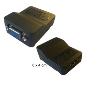
Adapters
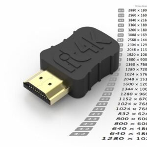
fit-Headless 4K is a miniature HDMI plug emulating a 4K display with 30 different resolutions
Fitlet Accessories
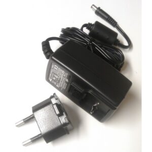
Strømforsyning til fitlet, fit-PC3/fit-PC3i med EU-plug (36W, 12VDC, 3A)
Adapters
fit-PC - Accessories
fit-PC - Accessories
fit-PC - Accessories
Airtop Accessories