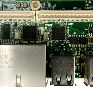
FM-XTDM2 (FM-2PCIE) Module
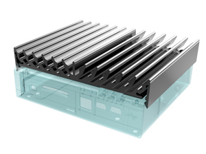
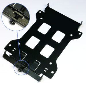
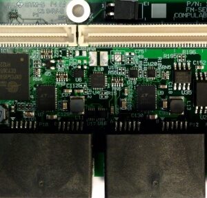
FM-XTDM2 FACE Module provide two optional mini PCI Express slots supporting either full or half size mechanical form factor. By default arrive with mechanical latches for full size modules, but can be adjusted for half size as well.
Refer to Compatibility Matrix for products fit.
Highlights
- 2x mini PCIe slots supporting mini PCI Express modules, featuring PCIe gen2 data rates (up to 5Gbps full duplex).
- Full/half size modules mechanical form factor
Hardware Specifications
mini PCI Express edge connector pinout
| mini PCI Express edge connector | |||||
|---|---|---|---|---|---|
| Pin # | Pin Name | Signal Description | Pin # | Pin Name | Signal Description |
| 1 | WAKE# | Open drain, active low signal driven low by a mini PCIe card to reactivate the PCIe link | 2 | 3.3Vaux | 3.3V power rail |
| 3 | COEX1/Reserved | Reserved for future wireless coexistence control interface between radios (if needed) | 4 | GND | Ground connection |
| 5 | COEX2/Reserved | 6 | 1.5V | 1.5V power rail | |
| 7 | CLKREQ# | Clock request – open drain, active low driven by mini PCIe card to request PCIe reference clock | 8 | UIM_PWR/Reserved | The UIM signals are defined on the system connector to provide the interface between the removable User Identity Module (UIM) Interface – an extension of SIM and WWAN. |
| 9 | GND | Ground connection | 10 | UIM_DATA/Reserved | |
| 11 | REFCLK- | Reference clock used to assist the synchronization of PCI Express interface timing circuits | 12 | UIM_CLK/Reserved | |
| 13 | REFCLK+ | 14 | UIM_RESET/Reserved | ||
| 15 | GND | Ground connection | 16 | UIM_VPP/Reserved | |
| Mechanical Notch Key | |||||
| 17 | Reserved/UIM_C8 | Reserved | 18 | GND | Ground connection |
| 19 | Reserved/UIM_C4 | Reserved | 20 | W_DISABLE# | Active low signal when asserted by the system disable radio operation. Reserved for future use. |
| 21 | GND | Ground connection | 22 | PERST# | Asserted when power is switched off and also can be used by the system to force HW reset |
| 23 | PERn0 | PCI Express differential receive pair | 24 | 3.3Vaux | 3.3V power rail |
| 25 | PERp0 | 26 | GND | Ground connection | |
| 27 | GND | Ground connection | 28 | 1.5V | 1.5V power rail |
| 29 | GND | Ground connection | 30 | SMB_CLK | Optional SMBus two-wire interface for Host/mini PCIe module communication |
| 31 | PETn0 | PCI Express differential transmit pair | 32 | SMB_DATA | |
| 33 | PETp0 | 34 | GND | Ground connection | |
| 35 | GND | Ground connection | 36 | USB_D- | USB Host Interface |
| 37 | GND | Ground connection | 38 | USB_D+ | |
| 39 | 3.3Vaux | 3.3V power rail | 40 | GND | Ground connection |
| 41 | 3.3Vaux | 3.3V power rail | 42 | LED_WWAN# | Active low output signals are provided to allow status indications to users via system provided LEDs |
| 43 | GND | Ground connection | 44 | LED_WLAN# | |
| 45 | Reserved | Reserved for future second PCI Express Lane | 46 | LED_WPAN# | |
| 47 | Reserved | 48 | 1.5V | 1.5V power rail | |
| 49 | Reserved | 50 | GND | Ground connection | |
| 51 | Reserved | 52 | 3.3Vaux | 3.3V power rail | |
| Weight | 0,000 kg |
|---|---|
| Dimensions | 0,00 × 0,00 × 0,00 mm |
[acf field="specification"]
FACE-module – FM-XTDM2
13 in stock (can be backordered)
650,00 kr. 812,50 kr.
FM-XTDM2
650,00 kr. 812,50 kr.
13 in stock (can be backordered)


